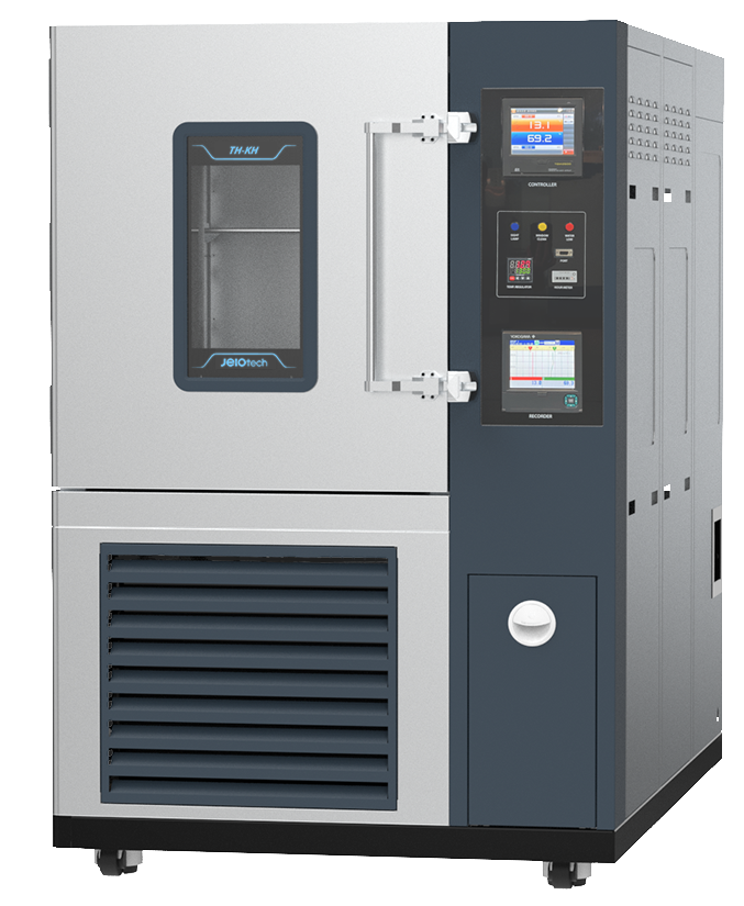
Temperature and humidity test chamber are no longer used simply to create hot and cold environments. They are widely applied in thermal cycling tests, accelerated aging simulations, and product reliability evaluations under harsh environmental conditions.
In many cases, the chamber still reaches the programmed temperature, and the displayed humidity remains stable, while the actual environment inside the test area gradually changes over time. Reduced airflow from circulation fans, aging door gaskets, or humidity sensors drifting out of calibration after extended use can all cause the chamber conditions to become less accurate than expected.
For testing involving lithium batteries, PCBs, electronic components, or composite materials, even very small deviations can significantly affect reliability evaluation results.
The Displayed Temperature May Not Be the Actual Sample Temperature
One common misconception is assuming that the temperature shown on the chamber display is the same as the actual temperature of the testing product.
In reality, the air inside the chamber may reach to 85°C quite quickly, while the sample still require additional time to absorb and stabilize temperature. Thermal lag is often much greater than expected when testing large metal parts, lithium batteries, or high-density PCB assemblies.
As a result, the chamber may indicate that the target temperature has been reached even though the core of the product is still continuing to heat up or change temperature.
Many tests appear to match the programmed thermal profile, yet the actual thermal conditions affecting the sample were never fully stabilized according to the intended test requirements.
For this reason, engineers performing advanced reliability testing often attach additional sensors directly to the sample instead of relying solely on the chamber’s internal temperature readings.
The Most Dangerous Errors Often Come From Humidity
Unlike temperature-related issues, humidity deviations rarely trigger immediate warnings. Instead, they gradually affect material aging, lead oxidation on electronic components, and electrochemical migration on PCBs.
An environmental chamber may continue displaying stable humidity values even while the humidity probe has already drifted out of calibration due to chemical vapors, unsuitable water quality, or prolonged condensation inside the system.
Another overlooked issue is micro-condensation inside the chamber. This extremely thin layer of moisture forms around cold metal surfaces or in poorly circulated airflow areas. It is nearly impossible to detect with the naked eye, yet it can still cause microscopic corrosion or interfere with high-density electronic circuits.
Temperature Distribution Inside the Chamber Is Not Perfectly Uniform
Air circulation inside a thermal shock chamber is far more complex than it appears. Because of this, temperature and humidity inside the chamber are rarely distributed evenly.
When test samples are oversized or improperly positioned, airflow can become obstructed and create localized temperature and humidity variations. This issue is especially common in multi-sample testing or when evaluating large battery packs and high-power electronic modules.
There have been cases where the same chamber, using the same thermal profile and the same product type, produced different aging results simply because the sample placement inside the chamber was changed.
That is why the specializing laboratories often apply strict sample positioning procedures rather than arranging samples based on convenience.
Temperature Transition Speed Is Becoming More Important Than Maximum Temperature
Climate test chamber are no longer evaluated solely by maximum temperature range or deep cooling capability. Factors such as temperature uniformity, airflow control, stabilization speed after thermal transitions, and condensation management are becoming far more important.
This shift is driven by increasingly complex material structures. Multilayer PCBs, lithium batteries, and composite materials are highly sensitive to thermal stress generated during repeated hot-to-cold transitions.
Many microcracks and solder failures do not occur while maintaining high temperatures. Instead, they develop during continuous temperature cycling between heating and cooling phases.