
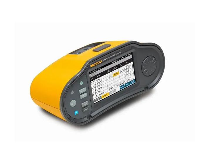
FLUKE 1674 FC Multifunction Installation Tester
Size: 26.25 cm x 14.19 cm x 11.93 cm (10.3 in x 5.6 in x 4.7 in)
Weight (including batteries): 1.6 kg (3.5 lb)
Battery type and capacity: BP290, Li-ion, 10.8 V, 2500 mAh, 27 Wh
Ingress Protection: IEC 60529: IP40
Safety: Complies with IEC/EN 61010-1, IEC 61010-2-030, IEC 61010-2-034
Safety rating: CAT III 600 V, CAT IV 300 V
Performance: IEC 61557-1 to IEC/EN 61557-8 and IEC 61557-10
Voltage measurement AC, DC and frequency
Range: 600 V
Resolution: 0.1 V
Input impedance: 320 kΩ
Overload protection: 660 V
Frequency: 45–66 Hz
Frequency resolution: 0.1 Hz
Input impedance: 320 kΩ
Continuity testing (RLO)
Range (Auto ranging): 20 Ω / 200 Ω / 2000 Ω
Resolution: 0.01 Ω / 0.1 Ω / 1 Ω
Open circuit voltage: > 4 V
Insulation resistance measurement (RISO)
Test voltages:
1672: 100 – 250 – 500 – 1000 V
1673 FC / 1674 FC: 50 – 100 – 250 – 500 – 1000 V
50 V
Insulation resistance range: 10 kΩ – 50 MΩ
Resolution: 0.01 MΩ
Test current: 1 mA at 50 kΩ
100 V
Insulation resistance range: 10 kΩ – 20 MΩ
Resolution: 0.01 MΩ
Test current: 1 mA at 100 kΩ
20 MΩ – 100 MΩ: resolution 0.1 MΩ
250 V
Insulation resistance range: 10 kΩ – 20 MΩ
Resolution: 0.01 MΩ
Test current: 1 mA at 250 kΩ
20 MΩ – 200 MΩ: resolution 0.1 MΩ
500 V
Insulation resistance range: 10 kΩ – 20 MΩ
Resolution: 0.01 MΩ
Test current: 1 mA at 500 kΩ
20 MΩ – 200 MΩ: resolution 0.1 MΩ
200 MΩ – 500 MΩ: resolution 1 MΩ
1000 V
Insulation resistance range: 100 kΩ – 200 MΩ
Resolution: 0.1 MΩ
Test current: 1 mA at 1 MΩ
200 MΩ – 1000 MΩ: resolution 1 MΩ
Insulation pretest
Requirement: Connections from the tester to L, N, and PE are required.
Surge Protection Device (SPD) – Insulation RAMP Test (IEC 61643-11)
Test voltage:
500 V – Step ramp 0 V to 500 V
Resolution: 1 V
Test current: 1 mA
Accuracy: ± (1.5 % + 3 digits)
1000 V – Step ramp 0 V to 1000 V
Resolution: 1 V
Test current: 1 mA
Accuracy: ± (1.5 % + 3 digits)
Insulation Monitoring Devices (IMD) – IEC 61557-8
Range: 1 kΩ – 10 kΩ, resolution 1 kΩ
10 kΩ – 100 kΩ, resolution 10 kΩ
100 kΩ – 3 MΩ, resolution 100 kΩ
Note: >1 MΩ only available with voltages >100 V
Loop and line impedance (ZI – No Trip and Hi Current)
Range setting:
10 Ω – resolution 0.001 Ω
Accuracy: Hi Current mΩ mode ± (2 % + 35 digits); No Trip (2 & 3 wire) ± (3 % + 6 digits)
20 Ω – resolution 0.01 Ω
Accuracy: Hi Current mode ± (2 % + 4 digits)
200 Ω – resolution 0.1 Ω
Accuracy: No Trip ± (3 %); Hi Current ± (2 %)
2000 Ω – resolution 1 Ω
Accuracy: ± 6 %
Notes:
(1) Valid for neutral resistance < 20 Ω and phase angle ≤ 30°, test leads must be zeroed before testing.
(2) 10 Ω range available on Fluke Connect™ 1674 FC model only.
(3) Valid for mains voltage > 200 V.
Prospective Earth Fault Current (PEFC) / Prospective Short Circuit Current (PSC)
Range: 0 kA – 50 kA
Resolution:
IK < 1000 A → 1 A
IK ≥ 1000 A → 0.1 kA
Computation: PEFC/PSC determined by dividing measured mains voltage by measured loop (L-PE) or line (L-N) resistance.
Voltage drop (by line impedance test)
Range: 0.0 % – 99.9 %
Resolution: 0.1 %
Accuracy: Consider accuracy of line impedance measurement
Note: Voltage drop reading calculated from line impedance measurement and entered current rating.
RCD tests – RCD types tested
RCD Type – 1672 / 1673 FC / 1674 FC
AC G: • / • / •
AC S: • / • / •
A, F G: • / • / •
A, F S: • / • / •
B, B+ G: – / • / •
B, B+ S: – / • / •
RDC-DD, RCD A/EV, RCD B/Mi: – / • / •
GFCI: • / • / •
RCD test inhibited for V > 265 V AC.
RCD tests permitted only if selected current × earth resistance < 50 V.
Legend:
AC – responds to AC
G – general, no delay
S – time delay
A – responds to AC and pulsed signals
F – responds to AC, pulsed, and high frequency
B, B+ – responds to AC, pulsed, high frequency, and smooth DC
RDC-DD – responds to residual currents of 6 mA DC
RCD tripping time test (ΔT)
Test function – RCD rated current
x½, x1: available for 10 mA, 30 mA, 100 mA, 300 mA, 500 mA, 1000 mA, Var
x5: available for 10 mA, 30 mA, 100 mA
Ramp: available for 10 mA, 30 mA, 100 mA, 300 mA, 500 mA, 1000 mA, Var
Auto: available for 10 mA, 30 mA, 100 mA
Mains voltage: 50 V – 265 V AC, 45–66 Hz
Type B RCDs require mains voltage 195–265 V.
Type AC RCDs only.
Type A RCDs limited to 700 mA, not available for Type B RCDs.
RCD tripping current (IΔN) measurement / Ramp Test
Current range: 30 % – 110 % of rated RCD current
Step size: 10 % of IΔN
Dwell time: 300 ms/step (Type G), 500 ms/step (Type S)
Accuracy: ± 5 %
Specified trip current ranges (IEC 61008-1):
30–150 % for Type A (IΔN > 10 mA)
30–210 % for Type A (IΔN = 10 mA)
20–210 % for Type B
50–100 % for Type AC
Earth resistance test (RE) – 1673 FC and 1674 FC only
Range: 200 Ω / 2000 Ω
Resolution: 0.1 Ω / 1 Ω
Frequency: 128 Hz
Output voltage: 25 V
Phase sequence indication
Range: 185 V – 600 V
Display: “1-2-3” or “3-2-1” for incorrect phase
Get exclusive volume discounts, bulk pricing updates, and new product alerts delivered directly to your inbox.
By subscribing, you agree to our Terms of Service and Privacy Policy.
Direct access to our certified experts