
A Physics Perspective: Not a Cable Fault, but a Reflection Problem
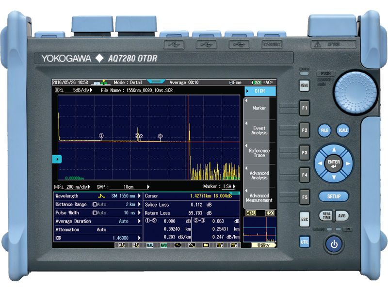
Fundamentally, an Optical Time Domain Reflectometer works by launching laser light pulses into an optical fiber and analyzing the light reflected back over time. Based on this return time, the instrument calculates distance, attenuation points, and abnormal events along the cable link. In other words, an OTDR does not directly “see” the fiber itself — it interprets the network through optical reflection signals.
The problem begins when the light pulse encounters a point with extremely high reflectance, commonly caused by a dirty UPC connector, an air gap, or poor physical contact. Instead of continuing smoothly through the fiber core, the light repeatedly bounces between highly reflective points. This phenomenon generates false return signals, causing the OTDR to mistakenly interpret them as additional events located farther away than they actually are.
That is why many fiber technicians encounter OTDR traces reporting faults at completely unrealistic locations, sometimes even beyond the actual length of the cable route. In reality, this is not a fiber break at all, but a Ghost Event — a false reflection event. These ghost events often appear according to mathematical multiples or combined distances between strong reflective points along the optical link.
The Best Defense Against Ghost Reflections: APC Connectors and Launch Fibers
- One of the biggest causes of OTDR ghost reflections lies in the type of connector used within the system. The two most common connector standards today — UPC and APC — differ significantly in how they handle reflected light, even though externally they mainly differ in color and connector end-face geometry.
UPC: Direct Reflection That Easily Creates Ghost Events
UPC connectors are typically blue and feature an almost perfectly flat polished end face. When reflected light returns, it travels nearly straight back toward the light source. In systems with multiple connectors or short transmission distances, this reflected energy can easily create false pulses on the OTDR trace. The issue becomes even more severe when connectors are dirty or not fully seated, causing reflectance levels to rise dramatically.
APC: Reflection Reduction Through Physical Angling
Unlike UPC connectors, APC connectors are green and designed with an angled polish of approximately 8 degrees. This angled design redirects reflected light away from the fiber core instead of sending it directly back toward the transmitter. As a result, reflectance is significantly reduced, greatly lowering the risk of ghost reflections. This is why FTTH systems, long-distance transmission networks, and high-stability optical infrastructures commonly favor APC connectors.
- The Critical Role of Launch Fibers: Without a launch fiber, multiple reflections near the input connector can overlap, making it very easy for technicians to confuse noise and reflection artifacts with real faults. A launch fiber stabilizes the outgoing pulse before it enters the main cable while also providing enough distance for the OTDR to separate the instrument dead zone from actual link events.
How to Distinguish Reflection Artifacts from Real Fiber Breaks
The most dangerous issue is not the presence of ghost reflections themselves, but technicians mistaking them for actual cable breaks. This can lead to unnecessary cable removal, splice closure inspections, or even road excavation. For this reason, correctly interpreting OTDR trace signatures is an extremely important skill when using an Optical fiber network test
Observe Signal Loss After the Event: A real event such as a faulty splice, fiber bend, or cable break always creates noticeable signal attenuation on the OTDR trace. After the event, the signal level drops, forming a visible “step-down” pattern. A ghost reflection, however, usually appears only as a tall reflective spike with little or no signal attenuation behind it. This is one of the most important physical indicators for identifying false reflections.
Check for Distance Repetition Patterns: Ghost reflections often appear in very characteristic patterns. For example, if a highly reflective connector is located at 500 meters, a ghost event may appear at 1000 meters or at positions related to the combined distances between reflective points. When reflection spikes repeat at mathematically consistent intervals, there is a very high probability that the signal is a reflection artifact rather than a real fault on the fiber link.
Try Changing the OTDR Pulse Width: When the pulse width on the OTDR is changed, real events usually change shape in a relatively predictable manner. Ghost reflections, however, often distort irregularly, become misshapen, or even disappear entirely when switching to a narrower pulse width.
The Ultimate Solution: Perform Accurate Testing from the Beginning
Most OTDR reflection problems are not caused by poor instrument quality, but by improper testing procedures. Standardizing measurement practices is therefore just as important as the technical specifications of the equipment itself.
Always Clean Connectors Before Testing
Microscopic dust particles on connector end faces can generate extremely high reflectance levels, even when invisible to the naked eye. Before every measurement, technicians should use dedicated fiber cleaning pens or lint-free wipes to clean all optical connectors.
Use Launch and Receive Fibers at Both Ends of the Link
A launch fiber helps the OTDR accurately identify the first connector event, while a receive fiber allows accurate evaluation of the loss at the final connector.
Control Reflectance at the Design Stage
In systems requiring high measurement accuracy, switching from UPC to APC connectors significantly reduces back reflections and improves OTDR measurement stability. In addition, low-quality connectors and worn-out adapters should be minimized as much as possible, since they are often the strongest sources of reflection across the entire optical link.
Nowadays, many OTDR meter distributed by EMIN Vietnam already integrate automatic Ghost Event detection algorithms. These systems can analyze reflection patterns, flag abnormal signals, and help technicians interpret OTDR traces more accurately, especially in complex optical networks with high connector density.